Helical gear design Theory and Numericals
Helical gear design theory question and answers
Helical gear design is concerned about the selection of material to finding the dimensions to fulfill the power transmission requirement.
Helical gear is a modified form of spur gear in which the teeth are cut at an angle. following are the question and answers related to the helical gear design.
Q.1. State the advantages and disadvantages of Helical gears.
Advantages of Helical gears
1. Helical gears operate more quietly and smoothly than the spur gears
2. Teeth of helical gears are stronger than the spur gear teeth.
3. Efficiency of helical gears is very high ( Upto 99 %)
4.These gears are suitable for high speed applications.
5. The contact ratio of these gears is higher than spur gears.
Disadvantages of helical gears
1. Helical gears are difficult to manufacture as compared to spur gear.
2. Helical gear exert an end thrust which is absorbed by thrust bearings.
3. In helical gears, the friction, heat generation and wear is high.
Application of helical gears.
Helical gears are commonly used in high speed automobile gear box, machine tool gear box, rolling mills, steam and gas turbines and other high speed application.
Q.2. Discuss the classification of Helical gears.
Helical gears can be classified into;


1. Helical gears: They are similar to spur gears but its teeth are cut at angle which is called as helix angle alpha with the axis of rotation of the gear. The helix angle angle of gear and pinion are same in magnitude but of different hands. For example right hand pinion meshes with left hand gear.
2. Herringbone gears : They look like two single helical gears one right hand and other left hand placed side by side. These gears reduce the end thrust acting on the thrust bearing.
Q.3. Explain the force analysis for helical gear design.
Following diagram gives force analysis of helical gear.
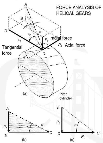
The resultant force P acting on the tooth of a helical
gear is resolved into three components, P t , P r and
P a as shown in Fig. 18.5(a), where
Pt = tangential component (N)
Pr = radial component (N)
Pa = axial or thrust component (N)
The normal pressure angle a n is in the plane ABC shaded by dots, while helix angle Y is in the lower plane BCD.
From the triangle ABC,
 …..(a)
 …..(b)
From The triangle BDC,
 …..(c)
 …..(d)
From Eqs (c) and (d),

From Eqs (a) and (d),

The tangential component is calculate from the relationship

 = transmitted torque (N-mm)
d = pitch circle diameter (mm)
In examples of gear tooth forces, it is often required to find out the magnitude and direction of the three components. The magnitudes are determined by using the following four equations,


where the suffix p is used for pinion.
The following information is required in order to decide the direction of the three components:
(i) Which is the driving element? Which is the driven element?
(ii) Is the pinion rotating in clockwise or anti- clockwise direction?
(iii) What is the hand of the helix? Is it right handed or left handed?
The directions of tangential and radial components are decided by the same method that is used for spur gears.
(i)Tangential Component (Pt)
(a)The direction of tangential component for a driving gear is opposite to the direction of rotation.
(b) The direction of tangential component for a driven gear is same as the direction of rotation.
(ii) Radial Component (Pr)
(a) The radial component on the pinion acts towards the centre of the pinion.
(b) The radial component on the gear acts towards the centre of the gear.
(iii)Thrust Component (P a ) The following guidelines can be used to determine the direction of the thrust component:
(a) Select the driving gear from the pair.
(b) Use right hand for RH-helix and left hand for LH-helix.
(c) Keep the fingers in the direction of rotation of the gear and the thumb will indicate the direction of the thrust component for the driving gear.
(d) The direction of the thrust component for the driven gear will be opposite to that for the
driving gear.
Q.4.Explain with neat sketch the concept of VIRTUAL number of teeth and its significance in the design of helical gear.
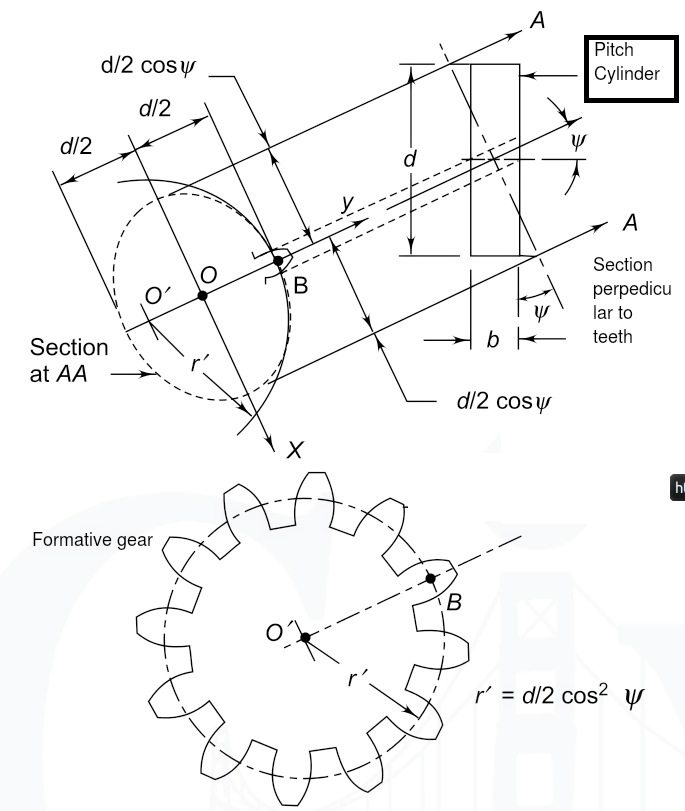
The pitch cylinder of the helical gear is cut by the
plane A–A, which is normal to the tooth elements
as shown in Fig. 18.3. The intersection of the plane
A–A and the pitch cylinder (extended) produces
an ellipse. This ellipse is shown by a dotted line.
The semi-major and semi-minor axes of this ellipse
are  and
and 
respectively. It can be
proved from analytical geometry that the radius of
curvature r' at the point B is given by,

where a and b are semi-major and semi-minor axes respectively. Substituting the values of a and b in
the expression for r', 
In the design of helical gears, an imaginary spur gear is considered in the plane A–A with centre at O' having a pitch circle radius of r' and module m n . It is called a ‘formative’ or ‘virtual’ spur gear. The pitch circle diameter d' of the virtual gear is given by,
The number of teeth z' on this imaginary spur gear is called the virtual number of teeth. It is given by  The number of teeth z' on this imaginary spur gear
is called the virtual number of teeth. It is given by,
 Hence putting z ,
NUMERICAL PROBLEMS ON HELICAL GEAR DESIGN
Type 1: Problems on Helical gear design geometry and its force analysis.
1) A pair of parallel helical gears consists of a 20 teeth pinion meshing with a 40 teeth gear. The helix angle is 25° and the normal pressure angle is 20°. The normal module is 3 mm. Calculate (i) the transverse module; (ii) the transverse pressure angle; (iii) the axial pitch; (iv) the pitch circle diameters of the pinion and the gear; (v) the centre distance; and (vi) the addendum and dedendum dia's.
------------------------------------------------------------------------------------------------------------------------
2) A pair of parallel helical gears consists of 18 teeth pinion meshing with a 63 teeth gear. The normal module is 3 mm. The helix angle is 23° while the normal pressure angle is 20°. Calculate (i) the transverse module; (ii) the transverse pressure angle; and (iii) the axial pitch.
------------------------------------------------------------------------------------------------------------------------
3) A pair of parallel helical gears consists of a 20 teeth pinion and the velocity ratio is 3 : 1. The helix angle is 15° and the normal module is 5 mm. Calculate (i) the pitch circle diameters of the pinion and the gear; iii) the centre distance.
------------------------------------------------------------------------------------------------------------------------
4) A pair of parallel helical gears consists of an 18 teeth pinion meshing with a 45 teeth gear. 7.5 kW power at 2000 rpm is supplied to the pinion through its shaft. The normal module is 6 mm, while the normal pressure angle is 20°. The helix angle is 23°. Determine the tangential, radial and axial components of the resultant tooth force between the meshing teeth
------------------------------------------------------------------------------------------------------------------------
5) A pair of parallel helical gears transmits A 5 kW power at 720 rpm is supplied to the pinion A through its shaft. The normal module is 5 mm and the normal pressure angle is 20°. The pinion has right-hand teeth, while the gear has left-hand teeth. The helix angle is 30°. The pinion rotates in the clockwise direction when seen from the left side of the page. Determine the components of the tooth force
Type 2: Problems on helical gear design finding Rated power/fs/strengths for a given helical gear.
6) A pair of parallel helical gears consists of a 20 teeth pinion meshing with a 100 teeth gear. The pinion rotates at 720 rpm. The normal pressure angle is 20°, while the helix angle is 25°. The face width is 40 mm and the normal module is 4 mm. The pinion as well as the gear is made of steel 4OC8 (S ut = 600 N/mm 2 ) and heat treated to a surface hardness of 300 BHN. The service factor and the factor of safety are 1.5 and 2 respectively. Assume that the velocity factor accounts for the dynamic load and calculate the power transmitting capacity of gears.
Type 3: Problems on Helical gear Design of gear(Finding module)
And other dimensions of Helical gear. {Buckinghum Equation}
9) A pair of parallel helical gears consists of 24 teeth pinion rotating at 5000 rpm and supplying 2.5 kW power to a gear. The speed reduction is 4 : 1. The normal pressure angle and helix angle are 20° and 23° respectively. Both gears are made of steel (Sut = 750 N/mm 2 ).The service factor and the factor of safety are 1.5 and 2 resp. The gears are finished to meet the accuracy of Grade 4.
(i) In the initial stages of gear design, assume that the velocity factor accounts for the dynamic load and that the face width is ten times the normal module. Assuming the pitch line velocity to be 10 m/s, estimate the normal module.
(ii) Select the first preference value of the normal module and calculate the main dimensions of the gears. (iii) Determine the dynamic load using Buckingham’s equation and find out the effective load for the above dimensions. What is the correct factor of safety for bending? (iv) Specify surface hardness for the gears, assuming a factor of safety of 2 for wear consideration.
10) The following data is given for a pair of parallel helical gears made of steel:
power transmitted = 20 kW , speed of pinion = 720 rpm ,
number of teeth on pinion = 35 number of teeth on gear = 70
centre distance = 285 mm , normal module = 5 mm , face width = 50 mm
normal pressure angle = 20°, ultimate tensile strength = 600 N/mm 2
surface hardness = 300 BHN , grade of machining = Gr. 6 ,service factor = 1.25
Calculate (i) the helix angle; (ii) the beam strength; (iii) the wear strength;
(iv) the static load; (v) the dynamic load by Buckingham’s equation;
(vi) the effective load; (vii) the effective factor of safety against
bending failure; and (viii) the effective factor of safety against pitting failure.
Answers [(i) 22.92° (ii) 19 930 N (iii) 21495.64 N (iv) 2792.19 N (v) 8047.29 N (vi) 11 537.53 N (vii) 1.73 (viii) 1.86]
Helical Gear design related links
- Log in to post comments